Session 9: servo motor, PWM, and ADC#
Goal#

Bonus#
TODO: fill
Servo Motor#

Servo motor is a type of electeric motor that is designed for precise control.
It is widely used in robotics.
We can control the position of the servo motor by sending a PWM signal to it.
In this session, we will be using a simple DC servo motor wich only take
angles in range of [-90, 90].
-90 when we send 1000us pulse, and 90 when we send 2000us pulse.
The desired PWM frequency for this servo motor is 50Hz.
This servo motor has three pins: VCC, GND, and signal.
We are connecting those pins like this:
VCC -> 5V (Fixed voltage)
GND -> GND
Signal ->
PD5of ATmega32
PWM#
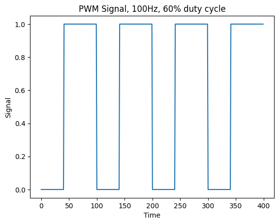
PWM (Pulse Width Modulation), is a technique for controlling the power delivered to a component.
In this technique we use different width of pulses in a signal.
These signals switch between 0 and 1.
The percentage of the time that a pulse is 1 is called duty cycle.
The pictures below show two examples of 100Hz PWM, one with the 30% duty cycle and the other 60%.

Create PWM on ATmega32#
We can create PWM using Timers on ATmega32.
We have three timers on Atmega32:
Timer0: 8bit
Timer1: 16bit
Timer2: 8bit
We can create PWM with all three timers.
As you can see on the picture below, each corresponding pin for each timer is shown.

Timer0:OC0->PB3
Timer1:OC1A->PD4OC1B->PD5
Timer2:OC2->PD7
In Timer0 and Timer2 for generating the desired frequency we only can use a prescaler which
could only take values of: [1, 8, 64, 256, 1024].
As you can see this numbers are limiting.
But for Timer1 in addition to a prescaler, we have another variable called ICR1 that can
be used to control the desired freqeuency which we are going to explain more about it later.
So to generate the desired frequency for our servo motor we will be using Timer1.
Timer1#
As we discussed in the previous session, we have three timers in Atmega32.
The only timer that is 16bit is Timer1.
We have some essential registers that we should use them to control the timer.
Also to put Timer1 in PWM mode, we need these registers that we are going to talk about them.
TCNT1A, TCNT1B#
These registers are used to store the current value of the timer.
OCR1A, OCR1B#
These registers are used to compare the value of the timer with them.
We can use these registers in different modes, specially in PWM mode to control the duty cycle.
ICR1#
This register is used to control the frequency of the timer.
In Fast PWM mode, we have this formula:
\(f_{PWM}\): desired frequency
\(f_{clk}\): clock frequency
\(N\): prescaler
\(ICR1\): value of
ICR1register
TCCR1A and TCCR1B#
Timer/Counter Register Description (TCCR) is a way that we control our timer setup.
For Timer1 we have two registers TCCR1A and TCCR1B.
TCCR1A |
7 |
6 |
5 |
4 |
3 |
2 |
1 |
0 |
|---|---|---|---|---|---|---|---|---|
name |
COM1A1 |
COM1A0 |
COM1B1 |
COM1B0 |
FOC1A |
FOC1B |
WGM11 |
WGM10 |
Read/Write |
R/W |
R/W |
R/W |
R/W |
R/W |
R/W |
R/W |
R/W |
initial value |
0 |
0 |
0 |
0 |
0 |
0 |
0 |
0 |
TCCR1B |
7 |
6 |
5 |
4 |
3 |
2 |
1 |
0 |
|---|---|---|---|---|---|---|---|---|
name |
ICNC1 |
ICEC1 |
- |
WGM13 |
WGM12 |
CS12 |
CS11 |
CS10 |
Read/Write |
R/W |
R/W |
R/W |
R/W |
R/W |
R/W |
R/W |
R/W |
initial value |
0 |
0 |
0 |
0 |
0 |
0 |
0 |
0 |
COM1A1/COM1B1 |
COM1A0/COM1B0 |
Description (in fast PWM mode) |
|---|---|---|
0 |
0 |
Normal port operation, OC1A/OC1B disconnected. |
0 |
1 |
WGM13:0 = 15: Toggle OC1A on Compare Match, OC1B disconnected (normal port operation). For all other WGM13:0 settings, normal port operation, OC1A/OC1B disconnected. |
1 |
0 |
Clear OC1A/OC1B on compare match, set OC1A/OC1B at BOTTOM, (non-inverting mode) |
1 |
1 |
Set OC1A/OC1B on compare match, clear OC1A/OC1B at BOTTOM, (inverting mode) |
Because we need to clear OC1A which is connected to PD6 get cleared every time
it reaches the value of OCR1A, we put it in the non-inverting mode.
TCCR1A |= (1 << COM1A1)
Mode |
WGM13 |
WGM12 (CTC1) |
WGM11 (PWM11) |
WGM10 (PWM10) |
Timer/Counter Mode of Operation |
TOP |
Update of OCR1x |
TOV1 Flag Set on |
|---|---|---|---|---|---|---|---|---|
0 |
0 |
0 |
0 |
0 |
Normal |
0xFFFF |
Immediate |
MAX |
1 |
0 |
0 |
0 |
1 |
PWM, Phase Correct, 8-bit |
0x00FF |
TOP |
BOTTOM |
2 |
0 |
0 |
1 |
0 |
PWM, Phase Correct, 9-bit |
0x01FF |
TOP |
BOTTOM |
3 |
0 |
0 |
1 |
1 |
PWM, Phase Correct, 10-bit |
0x03FF |
TOP |
BOTTOM |
4 |
0 |
1 |
0 |
0 |
CTC |
OCR1A |
Immediate |
MAX |
5 |
0 |
1 |
0 |
1 |
Fast PWM, 8-bit |
0x00FF |
BOTTOM |
TOP |
6 |
0 |
1 |
1 |
0 |
Fast PWM, 9-bit |
0x01FF |
BOTTOM |
TOP |
7 |
0 |
1 |
1 |
1 |
Fast PWM, 10-bit |
0x03FF |
BOTTOM |
TOP |
8 |
1 |
0 |
0 |
0 |
PWM, Phase and Frequency Correct |
ICR1 |
BOTTOM |
BOTTOM |
9 |
1 |
0 |
0 |
1 |
PWM, Phase and Frequency Correct |
OCR1A |
BOTTOM |
BOTTOM |
10 |
1 |
0 |
1 |
0 |
PWM, Phase Correct |
ICR1 |
TOP |
BOTTOM |
11 |
1 |
0 |
1 |
1 |
PWM, Phase Correct |
OCR1A |
TOP |
BOTTOM |
12 |
1 |
1 |
0 |
0 |
CTC |
ICR1 |
Immediate |
MAX |
13 |
1 |
1 |
0 |
1 |
Reserved |
– |
– |
– |
14 |
1 |
1 |
1 |
0 |
Fast PWM |
ICR1 |
BOTTOM |
TOP |
15 |
1 |
1 |
1 |
1 |
Fast PWM |
OCR1A |
BOTTOM |
TOP |
We need to put it on Fast PWM mode when we can control the frequency using ICR1.
So we have:
TCCR1A |= (1 << WGM11);
TCCR1B |= (1 << WGM12) | (1 << WGM13);
CS12 |
CS11 |
CS10 |
Description |
|---|---|---|---|
0 |
0 |
0 |
No clock source (Timer/Counter stopped). |
0 |
0 |
1 |
clkI/1 (No prescaling) |
0 |
1 |
0 |
clkI/8 (From pre-scaler) |
0 |
1 |
1 |
clkI/64 (From pre-scaler) |
1 |
0 |
0 |
clkI/256 (From pre-scaler) |
1 |
0 |
1 |
clkI/1024 (From pre-scaler) |
1 |
1 |
0 |
External clock source on T1 pin. Clock on falling edge. |
1 |
1 |
1 |
External clock source on T1 pin. Clock on rising edge. |
To make our calculation easier, we put our prescaler to 8 using the code below:
TCCR1B |= (1 << CS11);
Setup our simulation#
We do the following steps to setup our simulation for pwm.
Put an ATmega32 on the board.(make sure to connect its reset to a fixed volatage.)
set the clock frequency to 8MHz (in properties).
Then put a servo motor from Outputs/Motors/Servo Motor on the board.
Connect the
V+pin of the servo motor a 5V (fixed voltage).Connect the
GNDpin of the servo motor to the ground.Connect the
Signalpin of the servo motor to thePD5of the ATmega32.
Now our setup ready to write our code. But to make sure that we are making the right frequency and to see the pulses we also add an oscilloscope to our setup.
Put an oscope from Meters/Oscope on the board.
Connect the
CH1of the oscope to thePD5of the ATmega32.Connect the
GNDof the oscope to the ground.
So you are going to have something like this:

Write our code#
So at first let’s calculate the value of ICR1 to get the desired frequency.
We know our clock frequency is 8MHz and the desired frequency is 50Hz.
(Make sure to put board_build.f_cpu = 8'000'000L in the platformio.ini file.)
Also we put the prescaler to 8.
So we have:
Now we can write a function to intitiate our pwm.
void pwm_init()
{
  // Set PD5 as output
  DDRD |= (1 << PD5);

  // Make sure that there is no setup other than the one we are going to put
  TCCR1A = 0;
  TCCR1B = 0;

  // non-inverting mode
  TCCR1A |= (1 << COM1A1);

  // Fast PWM mode
  TCCR1A |= (1 << WGM11);
  TCCR1B |= (1 << WGM12) | (1 << WGM13);

  // Set prescaler to 8
  TCCR1B |= (1 << CS11);

  // Set the frequency to 50Hz
  ICR1 = 19'999;
}
Then we can control our servo motor using OCR1A.
So OCR1A=1000 would be -90 and OCR1A=2000 would be 90.
ADC#
ADC (Analog to Digital Converter) converts an analog signal to a digital signal.
We used to have only 1 or 0 in the digital world.
For example if our highest voltage was 5V, we could only have 5V or 0V.
But with ADC we can have a range of values between 5V and 0V.
In ATmega32 the resolution of the ADC is 10bit.
So we can have 1024 different values between 5V and 0V.
The formula to calculate the value of the analog signal is:
If our reference voltage would be 5V and we want to calculate
digital voltage when our analog voltage is 5V, we have:
And for 0V we have:
We have some registers that we should set in order to get the desired value from the ADC.
ADMUX#
ADC Multiplexer Selection Register (ADMUX) is used to select the channel of the ADC.
ADMUX |
7 |
6 |
5 |
4 |
3 |
2 |
1 |
0 |
|---|---|---|---|---|---|---|---|---|
name |
REFS1 |
REFS0 |
ADLAR |
MUX4 |
MUX3 |
MUX2 |
MUX1 |
MUX0 |
Read/Write |
R/W |
R/W |
R/W |
R/W |
R/W |
R/W |
R/W |
R/W |
initial value |
0 |
0 |
0 |
0 |
0 |
0 |
0 |
0 |
REFS1 |
REFS0 |
Description |
|---|---|---|
0 |
0 |
AREF, Internal Vref turned off |
0 |
1 |
AVCC with external capacitor at AREF pin |
1 |
0 |
Reserved |
1 |
1 |
Internal 2.56V Voltage Reference with external capacitor at AREF pin |
We should set the reference voltage to AVCC using the code below:
ADMUX |= (1 << REFS0);
ADLAR: ADC Left Adjust Result
MUX4 |
MUX3 |
MUX2 |
MUX1 |
MUX0 |
Single Ended Input |
|---|---|---|---|---|---|
0 |
0 |
0 |
0 |
0 |
ADC0 |
0 |
0 |
0 |
0 |
1 |
ADC1 |
0 |
0 |
0 |
1 |
0 |
ADC2 |
0 |
0 |
0 |
1 |
1 |
ADC3 |
0 |
0 |
1 |
0 |
0 |
ADC4 |
0 |
0 |
1 |
0 |
1 |
ADC5 |
0 |
0 |
1 |
1 |
0 |
ADC6 |
0 |
0 |
1 |
1 |
1 |
ADC7 |
By setting the MUX bits we can select the channel of the ADC.
For example if we want to select ADC1 we should set the MUX bits to 00000 using the code below:
ADMUX &= 0xF0;
ADMUX |= 1;
ADCSRA#
ADC Control and Status Register A (ADCSRA) is used to control the ADC.
ADCSRA |
7 |
6 |
5 |
4 |
3 |
2 |
1 |
0 |
|---|---|---|---|---|---|---|---|---|
name |
ADEN |
ADSC |
ADATE |
ADIF |
ADIE |
ADPS2 |
ADPS1 |
ADPS0 |
Read/Write |
R/W |
R/W |
R/W |
R/W |
R/W |
R/W |
R/W |
R/W |
initial value |
0 |
0 |
0 |
0 |
0 |
0 |
0 |
0 |
ADEN: ADC EnableADSC: ADC Start ConversionADATE: ADC Auto Trigger EnableADIF: ADC Interrupt FlagADIE: ADC Interrupt Enable
ADPS2 |
ADPS1 |
ADPS0 |
Division Factor |
|---|---|---|---|
0 |
0 |
0 |
2 |
0 |
0 |
1 |
2 |
0 |
1 |
0 |
4 |
0 |
1 |
1 |
8 |
1 |
0 |
0 |
16 |
1 |
0 |
1 |
32 |
1 |
1 |
0 |
64 |
1 |
1 |
1 |
128 |
To enable the ADC we should set the ADEN bit to 1 using the code below:
ADCSRA |= (1 << ADEN);
Then we set the prescaler to 128 using the code below:
ADCSRA |= (1 << ADPS0) | (1 << ADPS1) | (1 << ADPS2);
ADC#
This variable is 10bit and is used to store the value of the ADC.
It contains of two registers ADCL and ADCH.
Connect a potentiometer#
In order to create different voltages we can use a potentioemeter.
Put a potentiometer from Passive/Resistors/Potentiometer on the board.
Connect the
V+of the potentiometer to the5V(fixed voltage).Connect the
GNDof the potentiometer to the ground.Connect the
Signalof the potentiometer to theADC0of the ATmega32.
To see what voltage we are making we can add a voltmeter to our setup.
Put a voltmeter from Meters/Voltmeter on the board.
Connect the red pin of the voltmeter to the fixed voltage connected to the potentiometer.
Connect the back pin right beside the red pin to the
ADC0of the ATmega32.
Now we need to connect our reference voltage on ATmega32.
Connect the
AREFof the ATmega32 to the5V(fixed voltage).Connect the
AVccof the ATmega32 to the5V(fixed voltage).
So you are going to have something like this:

Write our code for ADC#
To initialize the ADC we can write the following function:
void adc_init()
{
    // Set reference voltage to AVCC
    ADMUX |= (1 << REFS0);

    // Enable ADC
    ADCSRA |= (1 << ADEN);

    // Set prescaler to 128
    ADCSRA |= (1 << ADPS0) | (1 << ADPS1) | (1 << ADPS2);
}
To read the value of the ADC we can write the following function:
uint16_t adc_read(uint8_t channel)
{
    // Set the channel
    ADMUX &= 0xF0;
    ADMUX |= channel;

    // Start the conversion
    ADCSRA |= (1 << ADSC);

    // Wait for the conversion to finish
    while (ADCSRA & (1 << ADSC))
        ;

    // Retrun the value
    return ADC;
}
Now we can use the adc_read function to read the value of the ADC
(which is between 0 and 1023).
Then cast it to 1000 to 2000 and put it in the OCR1A to control the servo motor.
(we can use map function to do this.)