Session 1: Introduction#
NSK108#
Is a board that is made for educational purposes. It is build by Noavaran Electronic. It supports AVR and MCS-51 microcontroller, In this class we are working on an AVR microcontroller, called Atmega32.

In the picture above, you can see the board that we are working on this class.
Programmer#
To program our code to the microcontroller, we are using ISP programmer. In the picture below you can see the programmer that we are using right now. We are connecting this programmer to our pc via usb port. Also, we connect the ISP to the board.

ATmega32#
ATmega32 is an 8-bit AVR microcontroller developed by Atmel (now Microchip Technology). Commonly used in embedded systems, robotics, and industrial automation due to its low power consumption and ease of use.
32 KB of flash memory
non-volatile
Where our program is stored
2 KB of SRAM
volatile
Where our variables, stack operations and buffer is stored
1 KB of EEPROM
non-volatile
Config that we want it to remain
32 general-purpose I/O pins
8-channel 10-bit ADC
3 timers (one 8-bit, two 16-bit)
UART, SPI, and I2C communication interfaces
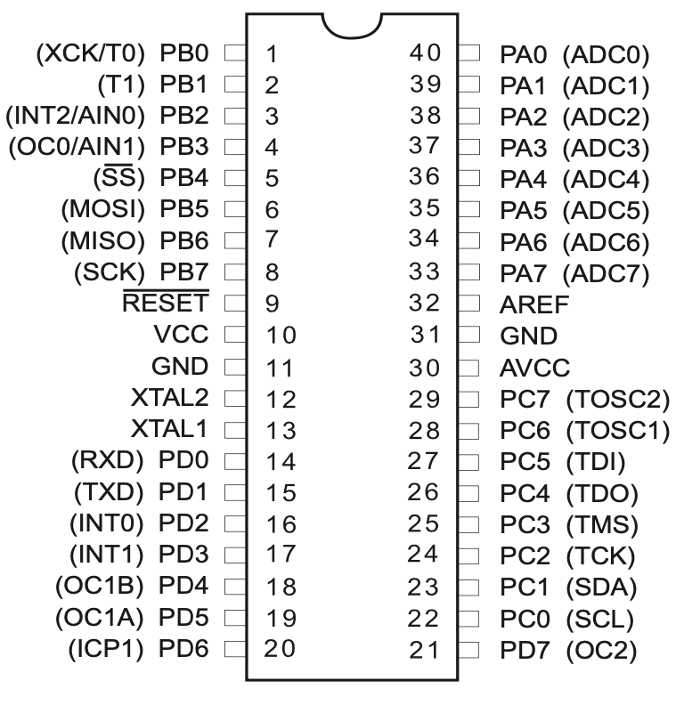
In the picture above, you can see the pins on ATmega32. There are 32 geneal-purpose I/O pins:
PA
PB
PC
PD
Each pin is connected to a component on the board which we are going to explain them in the according lesson. All of these 32 pins can be set as outputs or inputs. (using their DDR)
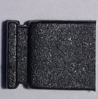
jumper#
A removable connector that is used to connect to pins on the board. There is an example of a jumper in the picture below.
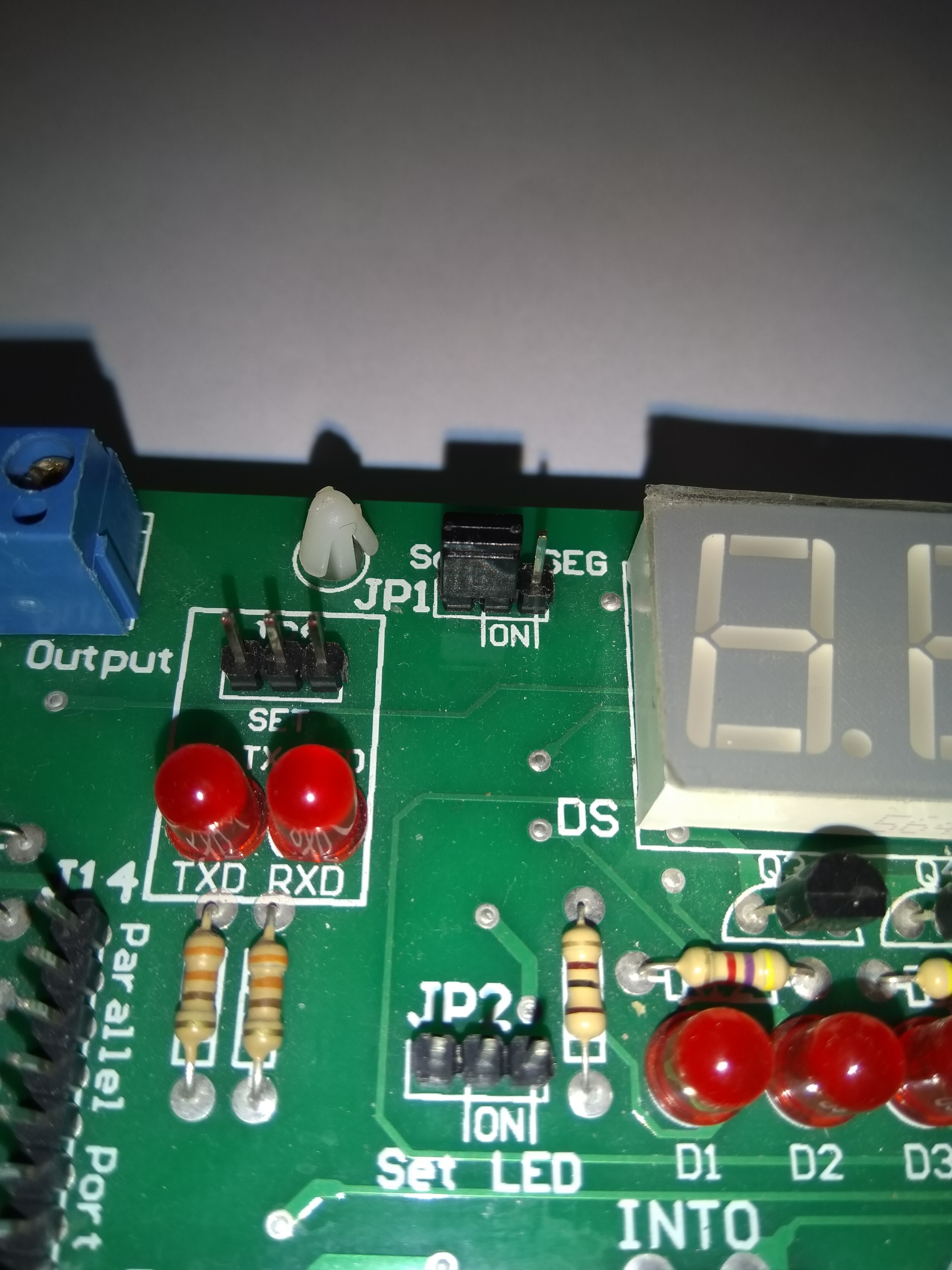
In this board most of the time there are 3 positions that you can put a jumper on:
on
off
none
The picture below shows the position of a jumper in “on” position in “JP1”.

Also, The picture below shows the position of a jumper in “off” position in “JP1”.
And lastly, The picture below has no jumper in “JP1”.

SimulIDE#
SimulIDE is a simplified IDE for simulating circuits. It is a free and open-source software and exteremly good for teaching purposes. More advanced IDEs are:
Proteus
Multisim
KiCad
To install SimulIDE you can simply download it from the link below:
Then extract the zip file and run the executable file.
PlatformIO#
PlatformIO is an open-source extension for Visual Studio Code. It is a well-kown IDE for embedded systems. It supports a wide range of microcontrollers and boards. We are using PlatformIO to write our code and make a hex file. Then we are using the ISP programmer to program the hex file to the microcontroller or we can use the simulator to simulate the code.
To install PlatformIO, first you should have visual studio code installed on your machine. Then you can go to the extensions tab and search for PlatformIO. After installing the extension, you can start a new project and select the board that you are working on. It will download all the necessary files needed for your project. In this course we are using the Atmega32 board. So when we are creating a new project, we are selecting ATMega32 as our board, like the picture below.

After our project is created, a folder will be created in the directory that you have selected. In this folder, you can see the “src” folder which contains the main.cpp file. We write our code in this file. The template that is created for us is like the code below:
#include <Arduino.h>

// put function declarations here:
int myFunction(int, int);

void setup() {
  // put your setup code here, to run once:
  int result = myFunction(2, 3);
}

void loop() {
  // put your main code here, to run repeatedly:
}

// put function definitions here:
int myFunction(int x, int y) {
  return x + y;
}
In the code above, you can see the setup and loop functions. These two functions are the ones that we are using, and we can delete the other functions. So we end up with the code like below:
#include <Arduino.h>

void setup()
{
}

void loop()
{
}
In setup function, we are initializing the pins and the components that we are using.
In loop function, we are writing the main code that we want to run repeatedly (it is like a while True).
To make the hex file, we can simply click on the “tick” icon on the bottom of the screen.
Then the hex file will be created in the “.pio/build/ATmega32” folder.
avrdude#
avrdude is a command-line tool that is used to program the hex file to the microcontroller.
To install avrdude on Ubuntu you can simply run the command below:
sudo apt install avrdude
Other linux distributions also contain avrdude that you can get them from their package manager. To program our code to the microcontroller, we can use the command below:
avrdude -c usbasp -p m32 -U flash:w:.pio/build/ATmega32/firmware.hex
A simple LED blink code#
To make a simple LED blink code, first we should put an LED on the board. To do that we do these steps:
Put an
led(Outputs/Leds/LED) on the board.Put a
fixed voltageon the board.Put a
groundon the board.Connect the
fixed voltageto theled’sanode(the longest pin).Connect the
groundto theled’scathode(the shortest pin).Click on the
fixed volatageto turn it on.Run the simulation.
So you should have something like this:

Now we have a working LED on the board.
Now let’s put an ATMega32 on the board and connect the led to the ATMega32.
To do that we do these steps:
Put an
ATMega32(Micro/AVR/ATMega32) on the board.Connect the
fixed voltageto theRstof theATMega32.Connect the
anodeof theLEDto thePB0of theATMega32.Conncet the
cathodeof theLEDto theground.
So you should have something like this:

Now let’s write the code to make the LED blink.
To do that we do these steps:
Create a new project in
PlatformIOby selectingATMega32as your board.Write the code below in the
main.cppfile.
#include <Arduino.h>

void setup()
{
    DDRB = 0x01;
    PORTB = 0x01;
}

void loop()
{
    PORTB = 0x00;
    delay(500);
    PORTB = 0x01;
    delay(500);
}
Click on the
tickicon to make the hex file.Go to SimulIDE and right click on
ATMega32and selectLoad HEX file.Select the hex file that you have created (.pio/ATMega32/frimware.hex) (you might need to select show hidden files).
Run the simulation.
So it should be something like this:

Now lets connect your board to our computer and upload our hex file using the code below:
avrdude -c usbasp -p m32 -U flash:w:.pio/build/ATmega32/firmware.hex
Important
Make sure the jumber (JP2) on the board is in the on position.