Session 7: External Interrupt#
Goal#


Bonus#


Patern above
Interrupt0: stop whenever it’s pressed
Connect LEDs#
Let’s first connect 8 LEDs to the PORTB of an ATmega32.
We can do that like below:

Now, write a code to turn on all the LEDs. After that let’s talk about interrupt.
Interrupt#
Interrupt is a special signal.
It tells the microcontroller to stop (halt)
what he is doing right now and execute some
special code.
This special code is in a Interrupt Service Routine Function.
In ATmega32 we have 3 external interrupts
which are connected to their special pins.
Those pins are shown in the table below:
Interrupt0 |
Interrupt1 |
Interrupt2 |
|---|---|---|
PORTD2 |
PORTD3 |
PORTB2 |
In this session, we will be working on
Interrupt0 and Interrupt1.
To use these interrupts we need 3 steps:
Tell microcontroller which interrupt we want to use
Enable global interrupts
Write the function
Imagine you are at your house. There is a switch at the beggining of your house that has a control on whether your house has electricity or not. This switch is like our second step. Now with that switch on, you can turn on the light of each specific room that you want. Each specific room is like our first step.
Now let’s explain how to tell microcontroller to do each of those steps.
Step 1 (Enable specific Interrupt)#
To enable an specific interrupt we use a
Register in ATmega32 called GICR.
GICR stands for General Interrupt Control Register.
Each bit on GICR does a specific task.
We only need to change bit 7 and 6,
To tell the microcontroller if we want to enable
Interrupt1 or Interrupt2.
The complete table is shown below:
bit |
7 |
6 |
5 |
4 |
3 |
2 |
1 |
0 |
|---|---|---|---|---|---|---|---|---|
name |
INT1 |
INT0 |
INT2 |
- |
- |
- |
IVSEL |
IVCE |
Read/Write |
R/W |
R/W |
R/W |
R |
R |
R |
R/W |
R/W |
initial value |
0 |
0 |
0 |
0 |
0 |
0 |
0 |
0 |
To enable Interrupt1 to work we put the value of the 7th index of GICR to 1,
to do so we can use a code like this:
GICR |= 1 << INT1;
In the code above INT1 is equal to 7.
In embedded programming to make the code more clean also
to help us not memorizing each bit, they have made some
special constants.
INT1 is one of them.
Respectively, we have INT0 for interrupt0
Step 2 (enable global interrupts)#
To enable global the interrupts, there is a function called
sei().
So the only thing that we have to do is to call this function.
Also to disable global interrupts, we can use a function called
cli().
Step 3 (Write a fucntion)#
To write a function for our specefic interrupt we can use the code below:
ISR(INT1_vect){
    // your code here
}
INT0_vect: for intrrupt 0INT1_vect: for intrrupt 1
The code that you write in this function
will be executed, if the interrupt1 has happened.
For example let’s write our function like below:
ISR(INT1_vect){
    PORTB = ~PORTB;
}
In the code above, anytime interrupt1 happens,
the value of PORTB will be reverted.
Now, we are ready to connect our interrupt to our microcontroller.
Connect Interrupt#
To connect an interrupt, we need to add a switch.
Connect one part of the switch to the PD3 and the other
part to a fixed voltage that is on.
Some thing like below:

Test our code on simulation#
Now we have a code like below:
#include <Arduino.h>

ISR(INT1_vect)
{
  PORTB = ~PORTB;
}

void setup()
{
  DDRB = 0xFF;

  GICR |= (1 << INT1);

  sei();
}

void loop()
{
}
In the code above we have implemented everything that we said before. And we expect that, every time that we apply an interrupt, LEDs toggle. If they are on, they should become off and vice versa.
But the output would be somethings like below:
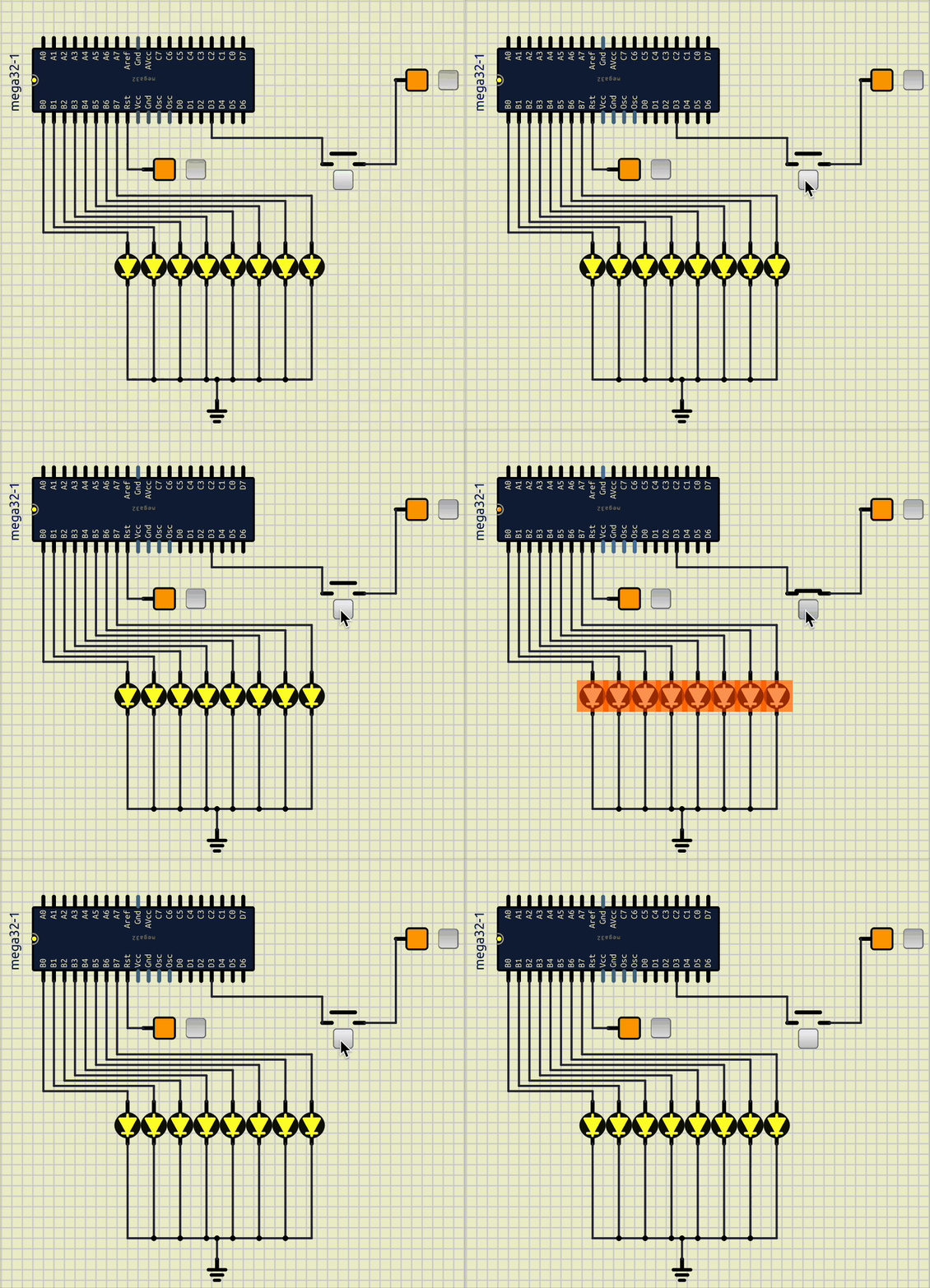
As you can see, anytime I press a key the output would be random.
To fix this issue we should know another registed called MCUCR.
MCUCR#
MCUCR stands for MCU Control Register.
ISC stands for Interrupt Sense Control.
It basically controls when should an Interrupt occur.
As you can see we can config our Interrupt to happen in different situations.
bit |
7 |
6 |
5 |
4 |
3 |
2 |
1 |
0 |
|---|---|---|---|---|---|---|---|---|
name |
SE |
SM2 |
SM1 |
SM0 |
ISC11 |
ISC10 |
ISC01 |
ISC00 |
Read/Write |
R/W |
R/W |
R/W |
R/W |
R/W |
R/W |
R/W |
R/W |
initial value |
0 |
0 |
0 |
0 |
0 |
0 |
0 |
0 |
ISC11 |
ISC10 |
Description |
figure |
|---|---|---|---|
0 |
0 |
The low level of INT1 generates an interrupt request. |
|
0 |
1 |
Any logical change on INT1 generates an interrupt request. |
|
1 |
0 |
The falling edge of INT1 generates an interrupt request. |
|
1 |
1 |
The rising edge of INT1 generates an interrupt request. |
|


ISC01 |
ISC00 |
Description |
figures |
|---|---|---|---|
0 |
0 |
The low level of INT0 generates an interrupt request. |
|
0 |
1 |
Any logical change on INT0 generates an interrupt request. |
|
1 |
0 |
The falling edge of INT0 generates an interrupt request. |
|
1 |
1 |
The rising edge of INT0 generates an interrupt request. |
|
Set interrupt request mode#
Now we know the problem was because of the interrupt being sent
all the time we were holding the interrupt button, we can fix it.
Know we put our interrupt1 in the rising edge mode with the code below:
MCUCR |= (1 << ISC10);
MCUCR |= (1 << ISC11);
After testing our code again the output would be something like below:

As you can see anytime we press the key an interrupt will be sent.
Write a counter on LEDs and control them with Interrupt1#
Now we can write a counter on LEDs which is incrementing until
we press Interrupt1.
When Interrupt1 is pressed, it resets and increamention starts
from the begining.
Add Interrupt0#
Now add the Interrupt0 to pause the increament.
And if you want a bonus point do the pattern in the bonus section.
Note
To see all the registers related to Interrupts you can refer to
notes section in this tutorial or you can refer to the ATmega32 datasheet.